
7-Segment & Dot Matrix
10 Segment Dual LED Light Display Module Bar Graph Ultra Bright Red Yellow Orange Colors Multi-colorRs 50
Cash on Delivery all over Pakistan · Free delivery in Islamabad & Rawalpindi above Rs 5,000
Order on WhatsApp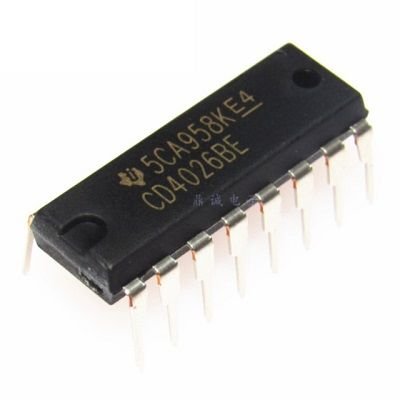
The IC CD4026 is an IC which can perform the function of both a counter as well a 7-segment Driver.
The IC CD4026 is an IC which can perform the function of both a counter as well a 7-segment Driver. One single IC can be used to count form zero (0) to nine (9) directly on a Common Cathode type 7-segment display. The count can be increased by simply giving a high clock pulse; also more than one digit (0-9) can be created by cascading more than one CD4026 IC. So if you have a 7-segment (CC) display on which you have to display numbers that are being counted based on some condition then this IC will be a perfect choice.
CD4026 7 Segment Counter is a 4000 series IC . This is a CMOS seven-segment counter IC and can operate at very low power. Its a decade counter, counts in decimal digits (0-9). It is use to display numbers on seven segment displays and it increments the number by one when a clock pulse applies to its PIN 1
Means more the clock pulse rate, faster the numbers change in 7 Segment Display. Below is the pin diagram and pin description of 4026 IC:
CD4026 7 Segment Counter Pin Configuration:
Number
Name
Description
1
Clock (CLK)
The counting happens when this clock pulse goes high, this pin is normally connected to 555 timer or other uC to produce a pulse
2
Clock Inhibit (INH)
Connected to the Ground (low) of the circuit, to enable clock pin
3


